Groundwater Flow Between Wells

Objectives: Identify the direction of groundwater flow using wells and quantify groundwater discharge (Q) and travel times through a confined aquifer.
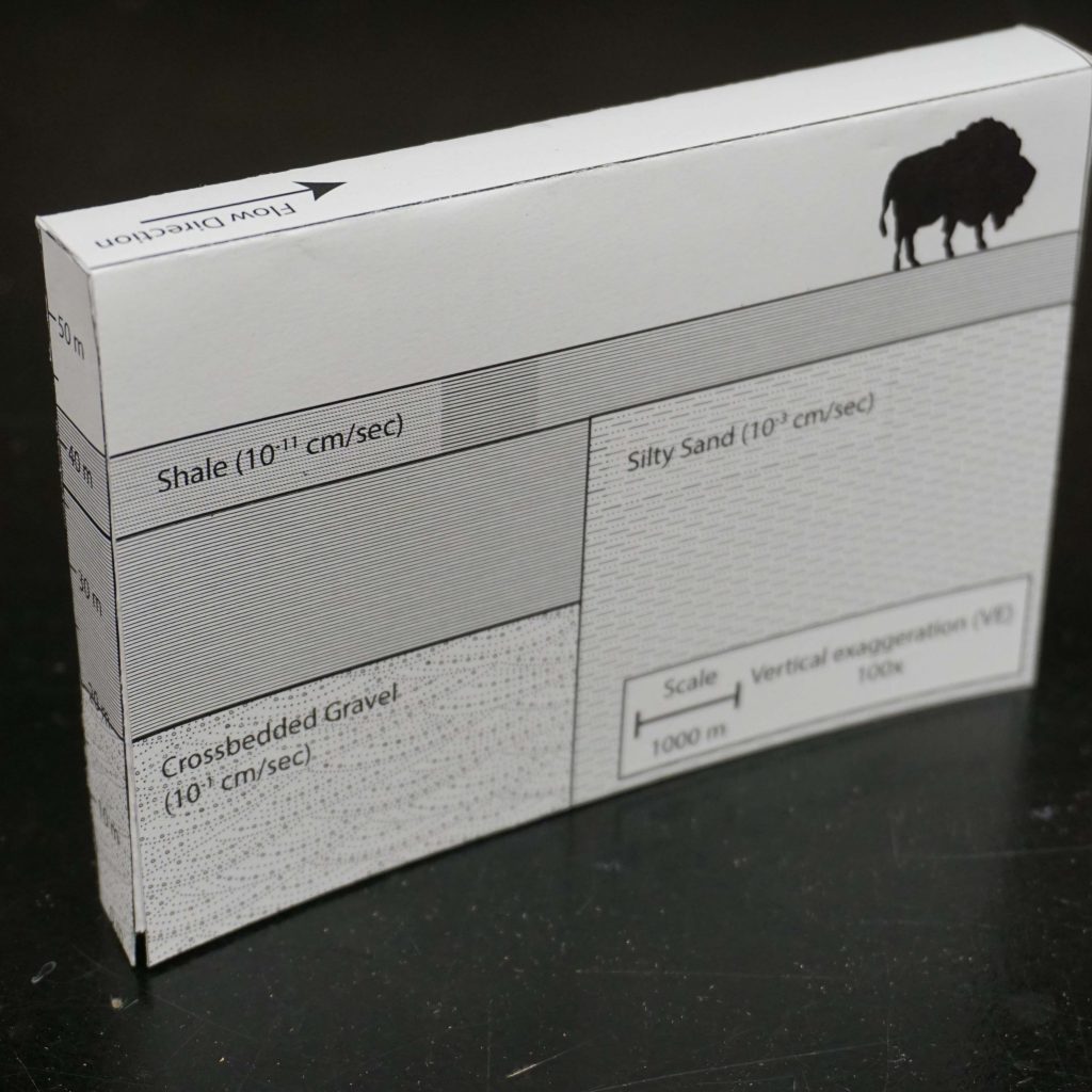
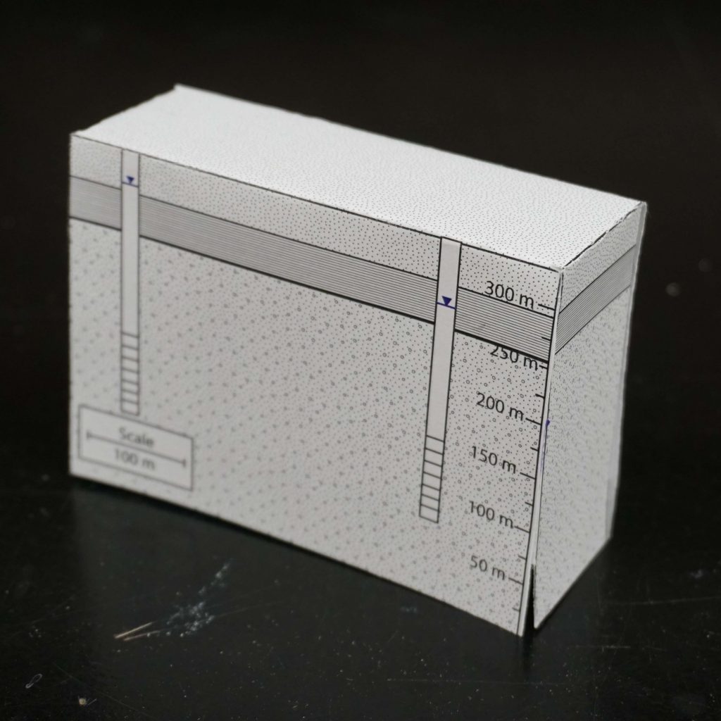
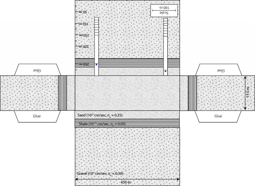
1. The following problem is based on confined gravel aquifer.  In this case the confining unit is a low hydraulic conductivity shale, which acts as barrier to groundwater flow in the vertical direction.  Within this aquifer there are two wells and the hydraulic head is shown as a solid line with a triangle on top.  The hydraulic conductivity and effective porosity are labeled on the folable aquifer model along with the dimensions of the model.  Please answer the following three questions.   

A. Using the water levels in the two wells as your guide determine the direction of groundwater flow in the confined aquifer. 

B.  Quantify the groundwater discharge through the confined aquifer in units of m3/s and then convert this discharge into gallons per day.

C.  Quantify the groundwater travel time between wells in units of days.
Creative Commons License


This work is licensed under a Creative Commons Attribution-NonCommercial 4.0 International License.
Darcy’s Law and Radial Coordinates

Objectives: Examine how Darcy’s law changes when transitioning to radial coordinates.

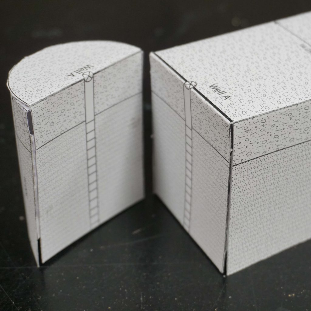
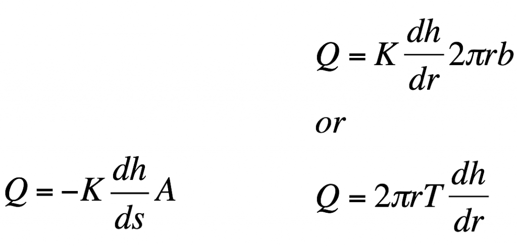
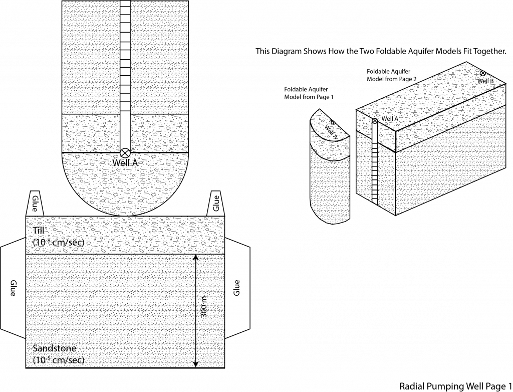
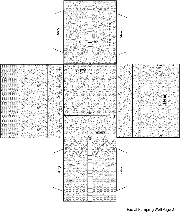
1. When a well is being pumped in a homogenous aquifer it is a lot easier to quantify drawdown at a given distance away from the well using radial coordinates.  This is because draw down away from the well is the same at any distance rx away from the well.  As a result, when dealing with a well that is being pumped we need to modify Darcy’s law from cartesian coordinates to radial coordinate (see equations below).  In the following problem we are going to assume that well A is a pumping well that has been pumping for a long time.  As a result, the water level is not changing with time and we can consider this a steady state problem.  The water levels in well A and B are given in the table below.  We are going to assume that the wells have a radius of 10 cm. Using the foldable aquifer model address the following problems.

Well Water Level (m)
Well A 385
Well B 395

A. Quantify the hydraulic gradient between well A and well B.   

B. Describe what the area term in Darcy’s law represents in the problem below, considering water is flowing between well A and well B.    

C.  Determine the pumping rate in m3/day that is necessary at well A to produce the drawdown described above.

Creative Commons License


This work is licensed under a Creative Commons Attribution-NonCommercial 4.0 International License.
Average Linear Velocity of Groundwater

Objectives: Determine the travel time of groundwater between two wells.

1. There are particular cases in Hydrogeology where it is helpful to determine the velocity of groundwater flow.  One application is to use the groundwater velocity to identify the travel time of a particle of water within an aquifer.  This can be very helpful when predicting the time it takes a contaminant to travel to a drinking water well.  In order to determine the velocity of groundwater flow it is necessary to know the specific discharge (q) and the area over which the groundwater is flowing through (i.e. the effective porosity).  Using the foldable aquifer model given below please answer the following questions.  Assume for this problem that the effective porosity of the gravel aquifer is 0.21 and the distance between well A and B is 550m. 

A. Identify is the direction of groundwater flow (i.e. Well A to B or Well B to A).

B. Quantify the travel time between wells in the gravel aquifer.

C. Determine the total groundwater discharge (Q) through the confined gravel aquifer.

Creative Commons License


This work is licensed under a Creative Commons Attribution-NonCommercial 4.0 International License.
Darcy Columns

Objectives: To explore the relationship between discharge (Q), specific discharge (q), and average linear velocity (v) in homogenous aquifers.

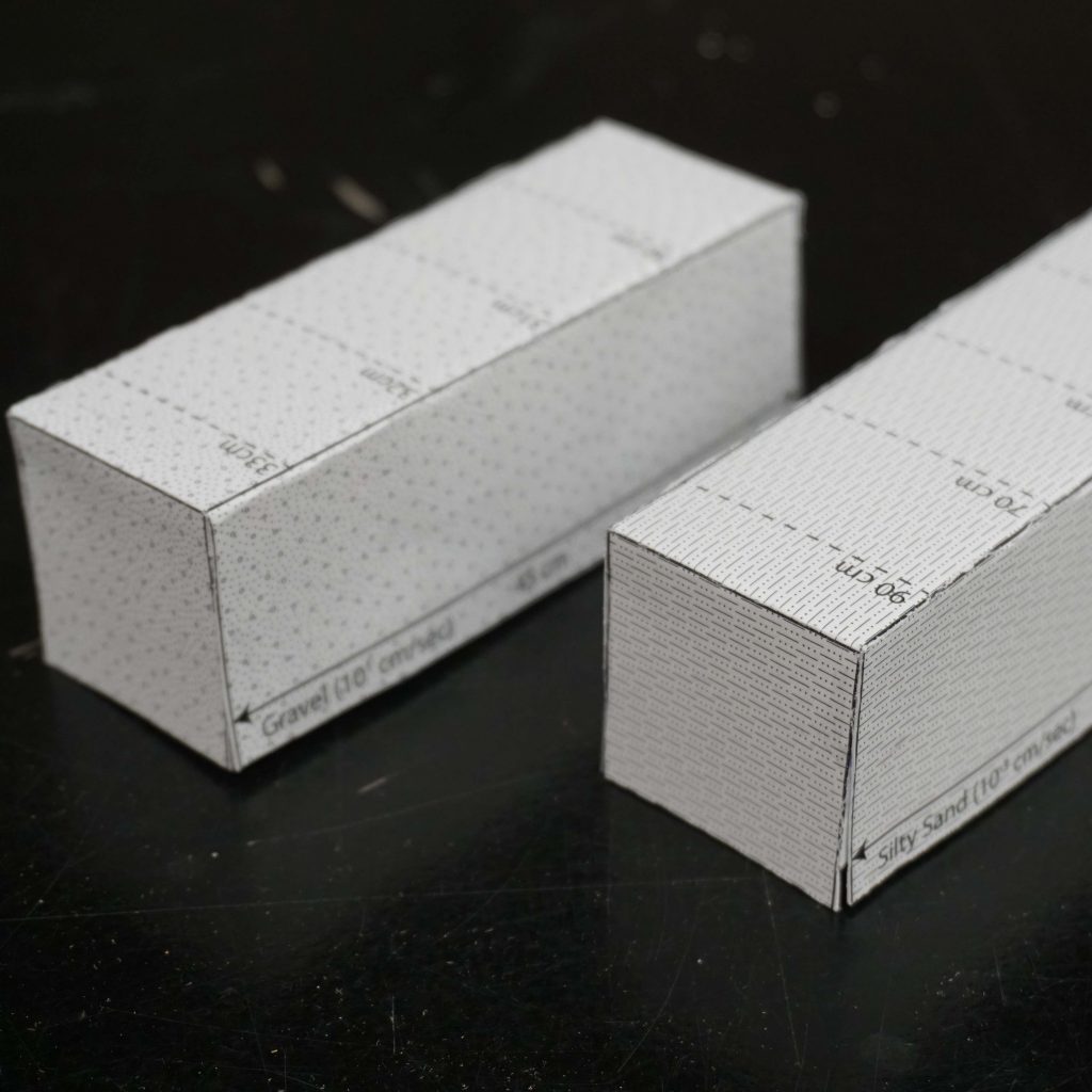
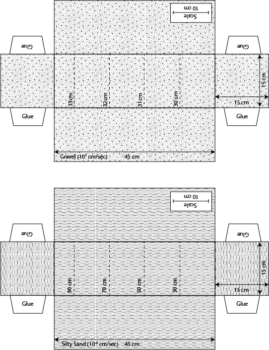
1. The following problem is based on water flow through two Darcy columns.  The first column is filled with a gravel that has a hydraulic conductivity of 101 cm/sec, and the second is filled with silty sand with a hydraulic conductivity of 10-3 cm/sec.  The equipotential lines are shown on the top of the models represented as dashed lines with their associated hydraulic heads.  Note that each column has a different distribution of equipotential lines. The total length of the columns are 45 cm and a scale bare is shown lower right corner of the back panel of the model.  Using these models please answer the following questions.

A. Based on the two Darcy’s columns provided quantify the difference in groundwater discharge [cm3/sec] between the Gravel column and the Silty Sand column. 

B.  Assuming the gravel column has an effective porosity of 0.30 and the silty sand column has an effective porosity of 0.25.  Determine which column has a higher average linear velocity and by how much. 

C.  Explain which of the following column would make a better aquifer.

Creative Commons License


This work is licensed under a Creative Commons Attribution-NonCommercial 4.0 International License.
Three Point Problem

Objectives: Identify the direction of groundwater flow in two dimensions and quantify the specific discharge in an unconfined aquifer.

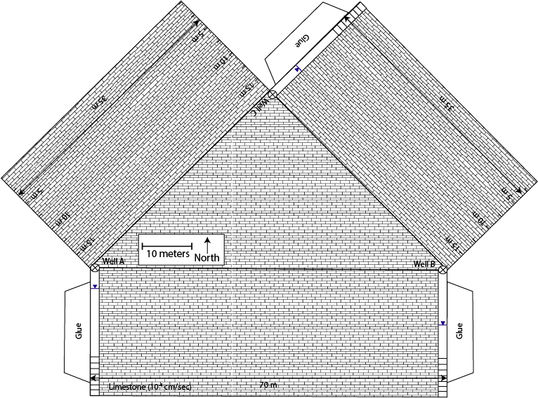
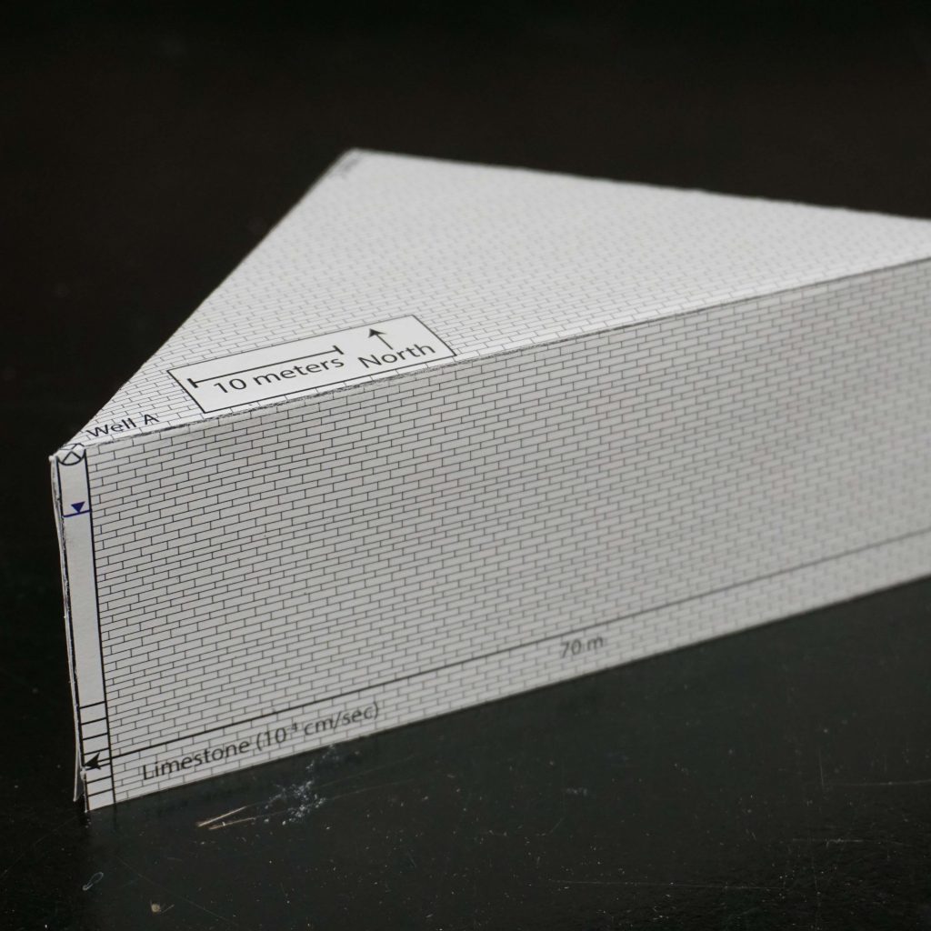
1. The following problem contains of an unconfined limestone aquifer with three monitoring wells.  The monitoring wells are positioned at each of the corners of the triangular aquifer.  Using the water levels shown in wells complete the following tasks.  

A. Determine the direction of groundwater flow based on the water levels in wells A-C. 

B.  Calculate the groundwater gradient across the unconfined aquifer.

C.  Quantify the specific discharge (q) in the unconfined aquifer.

Creative Commons License


This work is licensed under a Creative Commons Attribution-NonCommercial 4.0 International License.
Hydraulic Head Across Aquifers

Objectives: Determine the hydraulic head across an aquifer system with two distinct hydraulic conductivities.


1. As water flow from one aquifer to another aquifer with differing hydraulic conductivities there must be a change in hydraulic head or a change in discharge.  In the problem below, we are going to assume that water flow from Well A to Well C, through a two-aquifer system.  Both aquifers are confined by an upper shale unit and the discharge (Q) through the aquifers is 20 m3/day.   Using the foldable aquifer model address the following problems.

A. Determine the hydraulic head in Well B. 

B.  Determine the hydraulic head in Well C.

C.  Identify if the aquifer at Well C is confined or unconfined based on the water level in the well.

Creative Commons License


This work is licensed under a Creative Commons Attribution-NonCommercial 4.0 International License.
Groundwater Storage

Objectives: Explore the relationship between confined and unconfined aquifer storage properties.

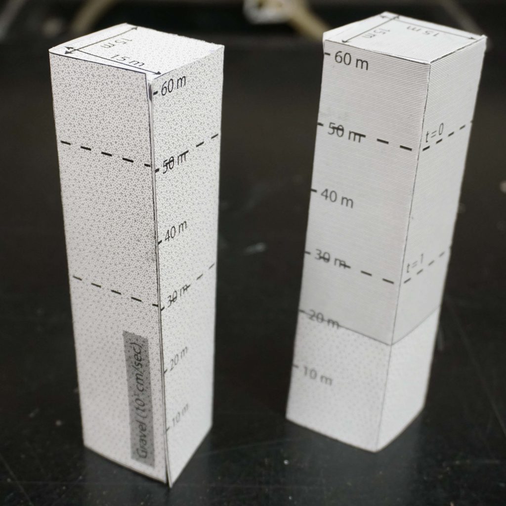
1. Groundwater storage is defined by the term storativity ( or storage coefficient), which represents the volume of water released from an unit area aquifer due to a unit drop in head.  This can be thought of as the volume of water (m3) drained from an aquifer that has an areal extent of one square meter and a decline of head of one meter.  However, the mechanisms for this draining of the aquifer a different for a unconfined aquifer as compared to a confined aquifer.  As a result, we have to sub-terms for which specific yield describes storage in a unconfined aquifer and specific storage describes storage in a confined aquifer.  Below is the equation that relates these two sub-terms to storativity:

Where:

Vw is the volume of water released form the aquifer [L3]

h is the hydraulic head [L]

A is the areal area of the aquifer you are evaluating [L2]

Ss is the specific storage [1/L]

b is the aquifer thickness [L]

Sy is the specific yield [-]

Using the foldable aquifer models given below answer the following questions assuming that the volume of water released in each of the aquifers is 945 m3.

A. Quantify the specific yield in the unconfined aquifer.

B. Quantify the specific storage in the confined aquifer.

C. Describe the difference between the storage mechanism in the unconfined aquifer as compared to the confined aquifer.

Creative Commons License


This work is licensed under a Creative Commons Attribution-NonCommercial 4.0 International License.
Porosity and Grain Packing

Objectives: Determine the relationship between grain packing and porosity of an aquifer.
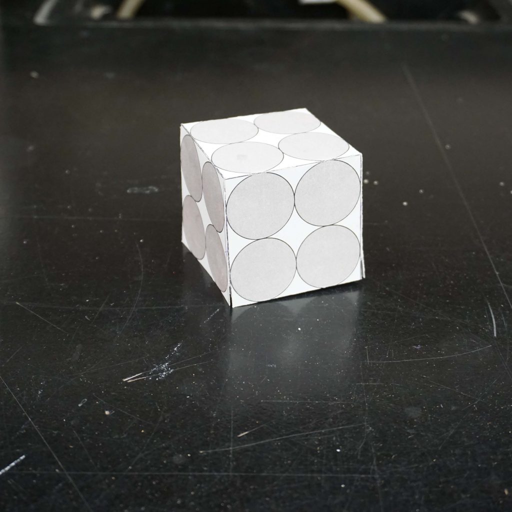
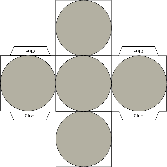
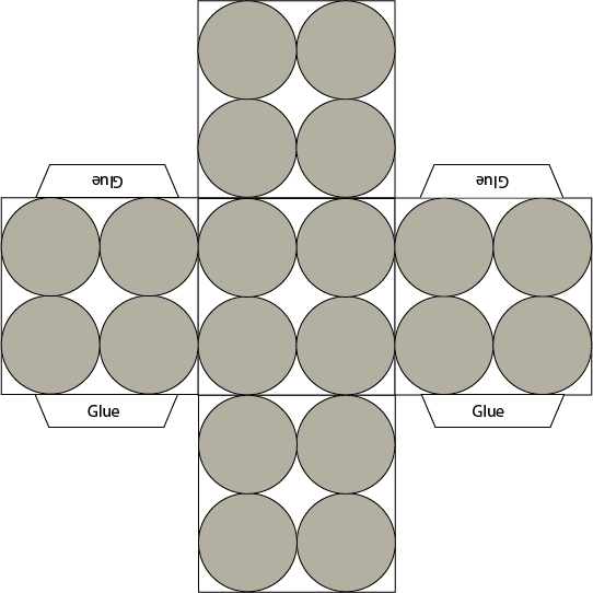
1. Porosity describes the percentage of void space in a cubic unit (volume) of an aquifer.  This porosity is controlled by the packing (geometry) of grains.  In this problem we are going to explore the simplest of packing: Cubic Packing.  As a warm up we will first look at the porosity of a single grain of sand inside a cubic value of aquifer.  The second part of this problem will explore cubic packing with eight grains inside a square volume of aquifer. Use the foldable aquifer model provided to answer the following questions.

A. Determine the porosity of the cubic aquifer with a single spherical grain.

B. Determine the porosity of an aquifer with cubic packing.

C. Explain the relationship between the porosity of the single spherical grain model and the cubic pacing model with eight grains. 

Creative Commons License


This work is licensed under a Creative Commons Attribution-NonCommercial 4.0 International License.
Example Foldable Aquifer Model

The goal of these paper aquifer models is to enable the user to easily visualize the three dimensional nature of groundwater related problems.  For many problems it is helpful to have a physical model that one can hold in order to better understand the problems being asked.  The hope is that these paper aquifer models will clarify concepts in groundwater science.  This brings up a relevant quote by statistician George Box:

“Essentially, all models are wrong, but some are useful” – Box

The hope here is that these models will be useful in understanding groundwater flow in three dimensions.

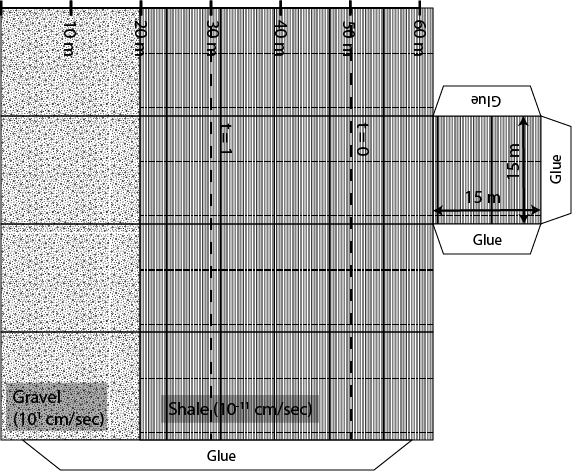
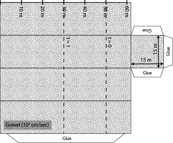
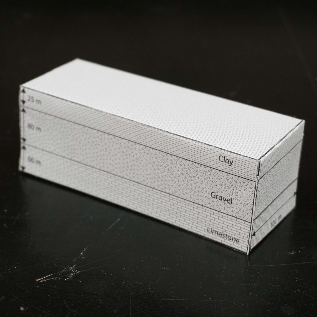
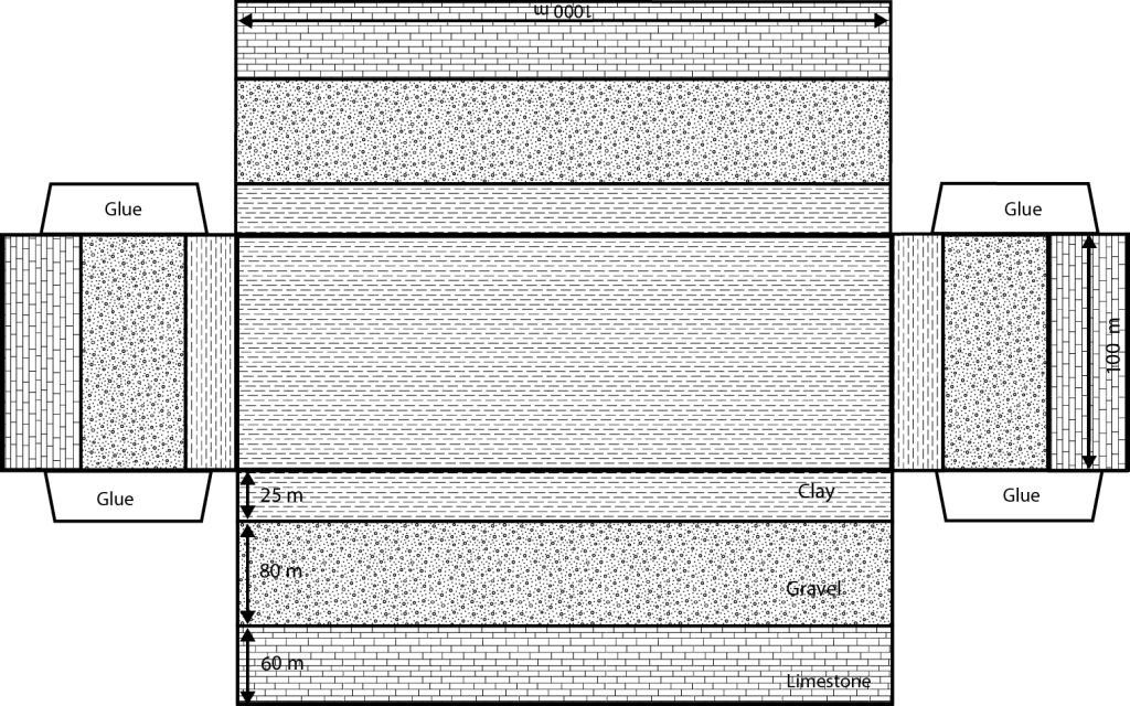
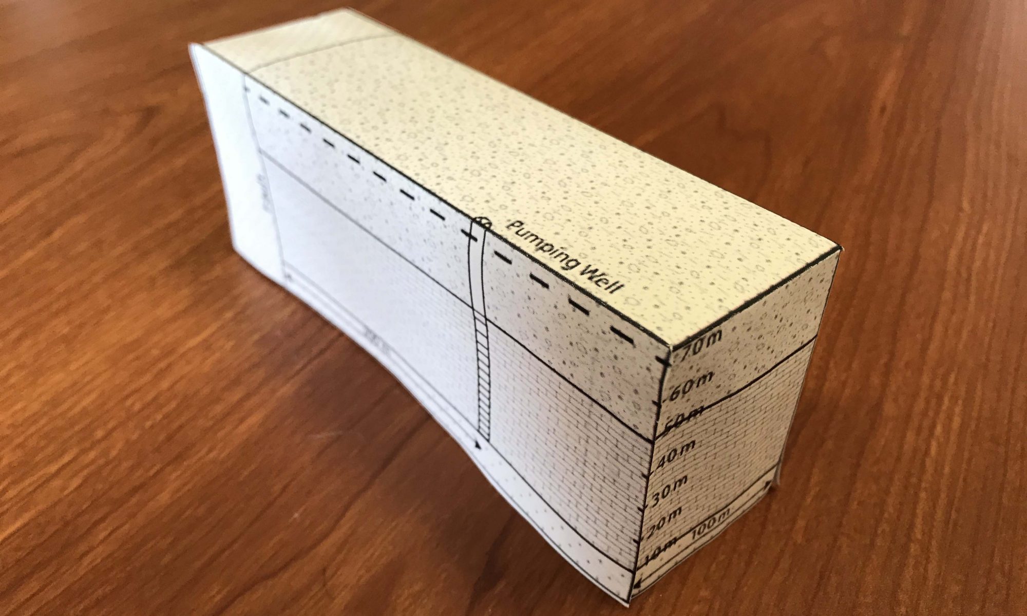
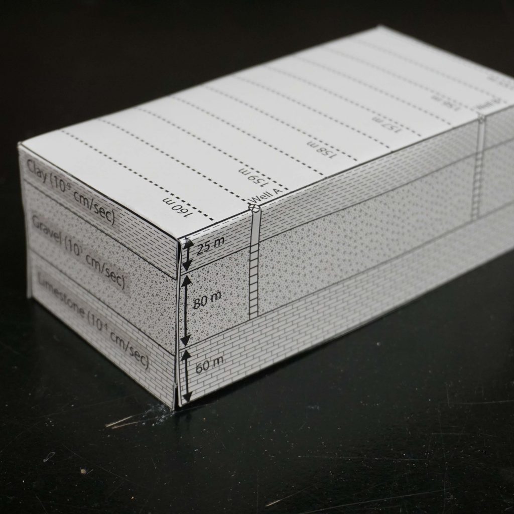
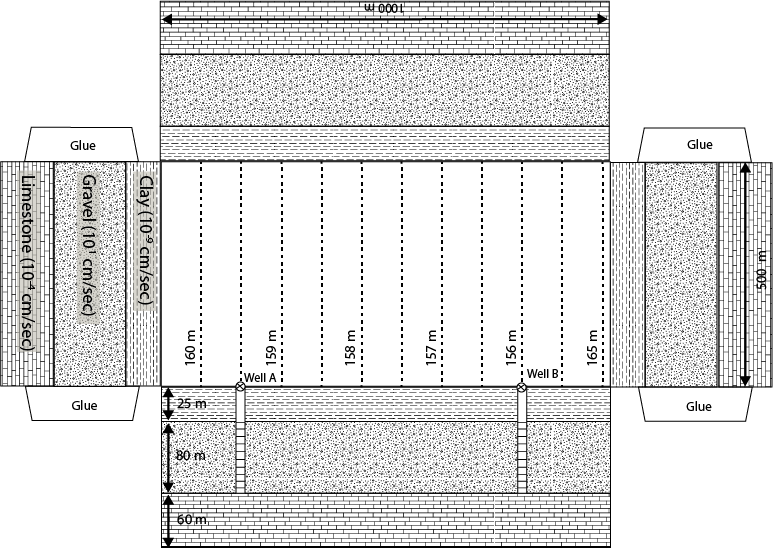
Each of the paper aquifers in this set of examples will need to be constructed by the user and are sized to be printed on a standard sheet of paper.  After printing the aquifer it is necessary to cut along the outer most edge of the model.  Then fold each of the outer panels along the solid lines.  This should form a three dimensional box or polygon.  The example show below will result in a rectangular box.  Each model has tabs or wings on the outer edge, which are meant to have glue or tape applied to help hold the model together.  A representation of one of these models is show below along with a link to download a PDF version to experiment with.

Example Foldable Aquifer

Each paper model has a specific lithology (geologic layering) which for future calculation will have an associated hydraulic conductivity.  As a reminder, hydraulic conductivity is simply a measure of the resistance to flow of water in a rock (it is a lot like resistance to the flow of electrical current in a circuit).  The paper model also has lines with arrows showing the length, width, and height of the lithologic layers.  At times and for specific problems there will be the need to apply a vertical exaggeration to these models.  Pay special attention to the stated dimensions of these models because they will have to change from one problem to the next. 
I would encourage the user to give this example model a try.  It is a quick model to construct and it will provide some experience as to how to construct future models in this project. 

Side note:  It should be stated that these are models and models are not perfect.  There will be times in working some of the upcoming problems where the user will need to use a bit more of their imagination to fully visualize the problem. 

Creative Commons License


This work is licensed under a Creative Commons Attribution-NonCommercial 4.0 International License.
Motivation for the Foldable Aquifer Project

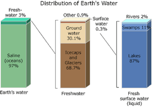
Water is one of our most important natural resources, yet it is almost invisible to the general public. Unless a person runs out of water they almost never think about its value. Public utilities effectively give it away for free, in principle only charging the cost of energy to pump it to your house. However under a changing climate, water will likely become one of the major resources of trade and unfortunately conflict. This is the motivation for training the next generation of scientists, managers, and general public on the basic principles that govern water resources. In particular, there is a strong interest in water that his held underground. This water that is held underground is termed groundwater and represents a volume of water much large than all the worlds fresh water held in lakes and rivers combined. The volume of groundwater is second only to the amount of water held in ice and glaciers. As a result of groundwater being held below the surface of the earth it is protected and typically represent a high quality resource.

In training the next generation of groundwater keepers there are a handful of basic principles that guide us in the movement and storage of groundwater resources.  These principles are not complicated and can be described on the most basic level in the statements listed below:

  • Groundwater flows from high energy to low energy (high to low hydraulic head)
  • Storage groundwater is governed by conservation of mass (in – out = change in storage)

While the statements listed above may seem simple, the complexity in the study of groundwater increases as we deal with space and time.  Groundwater is held in the void space between rocks or grains of sediment.  These rocks and sediment come in all sorts of shapes and sizes, which results in three dimensional problems.  In addition, water can be added or removed from the ground through natural and human interactions that occur at a range of time scales.  As a result, scientists, managers, and general public need to be able to visualize these process in three dimensions through time.

The goal of this project is to develop a set of resources that allow those interested in groundwater science to better visualize the three dimensional aspects of groundwater flow.  This visualization will be achieved through a series of foldable three dimensional paper models.  Each paper model will come with a series of problems to be solved to help reinforce the basic governing principles of groundwater flow.  While this is not meant to be an exhaustive study of groundwater science, it is a goal to try to cover as many useful examples as possible.

Please enjoy the journey into the Foldable Aquifer Project.